Measuring Tools
Fluke Pro Electric Pressure Calibrator
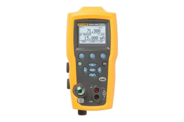
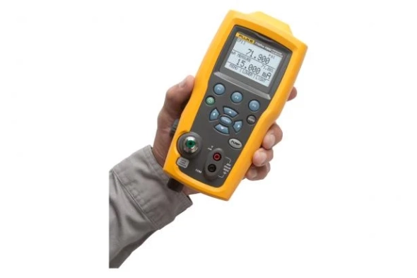
Fluke 719Pro Electric Pressure Calibrator sources, simulates, and measures mA signals and more
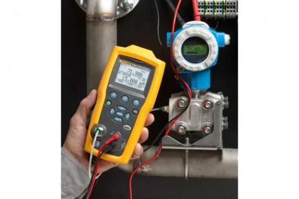
The 719Pro includes a full functioning loop calibrator that sources, simulates and measures mA signals and more making it the ideal test tool for calibrating high accuracy transmitters, pressure switches and pressure gauges.
Get the ultimate in measurement flexibility with the large backlit screen, which displays three parameters at once:
- Pressure measurement from internal or external sensor
- Sourced/simulated or measured mA values
- Temperature measured by optional RTD probe
Download
Produk Lainnya
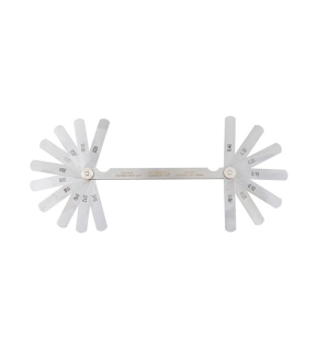
Hardened and polished taper blades enclosed in a steel case. Blades are clearly marked for easy reading and are manufactured to DIN 2275.
Features and Benefits
• Hardened and polished blades for increased tool life
• Blades are clearly marked for easy readings
• Supplied in a steel case for easy storage and portability
Standards
• DIN 2275
Notes
• Blade length: (75mm/3")
• Metric: (0.05mm - 0.5mm)
• Inch: (0.0015" - 0.025")
Features and Benefits
• Hardened and polished blades for increased tool life
• Blades are clearly marked for easy readings
• Supplied in a steel case for easy storage and portability
Standards
• DIN 2275
Notes
• Blade length: (75mm/3")
• Metric: (0.05mm - 0.5mm)
• Inch: (0.0015" - 0.025")
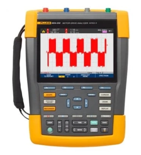
Simplify complex motor drive troubleshooting with guided test setups and automatic drive measurement that provide reliable, repeatable test results.
The Fluke MDA 550 Motor-Drive Analyzer saves time and the hassle of setting up complex measurements, and simplifies the troubleshooting process. Simply select a step-by-step guided test and measurement will show you where to make voltage and current connections, while preset measurement profiles ensure you will get all the data you need for every critical motor drive part, from input to output, the DC bus, and the motor itself . Doing simple to complex measurements? MDA-550 can do it. What's more, making reports before (as-found) and after (as-left) repairs or adjustments becomes more practical. This is all thanks to its built-in report generator feature.
The MDA-550 is an ideal portable motor drive analysis testing tool. Not only that, this tool can also be used to safely detect and solve common problems in inverter-type motor drive systems.
- Measures main motor drive parameters , including voltage, current, DC bus voltage level and AC ripple, voltage and current unbalance and harmonics, voltage modulation, and motor shaft voltage discharge.
- Performs broader harmonic measurements to identify the impact of low and high order harmonics on your power system.
- Performs guided measurements of motor drive input, DC bus, drive output, motor input, and shaft measurements with step-by-step graphical diagrams of voltage and current connections.
- Uses simple measurement settings with preset measurement profiles to automatically trigger data collection based on the selected test procedure.
- Quickly and easily generate reports that are perfect for documenting problem solving and collaborative work with others.
- Measure additional electrical parameters with a complete 500 MHz oscilloscope, meter and logger capability for a wide range of electrical and electronic measurements in industrial systems
The Fluke MDA-550 Motor Drive Analyzer uses guided test measurements to make analysis even easier
Drive input
Quickly measure input voltage and current to see if values ??are within acceptable limits by comparing the rated voltage to the actual supply voltage. It then checks the input current to determine if the current is within its maximum rating and the conductor size is appropriate. You can also check if the harmonic distortion is within an acceptable level. There are two options for doing this: carefully examine the shape of the waveform or look at the harmonics spectrum screen which displays total harmonic distortion and individual harmonics.
Imbalance of voltage and current
Check the voltage unbalance at the input terminals so you can make sure the voltage unbalance is not too high (> 6-8%), and the phase rotation is correct. You can also check for current unbalance, as too large an imbalance can indicate a driving rectifier problem.
Wider harmonic measurement
Excess harmonics are not only a threat to your rotating machine, but also to other equipment connected to the mains power system. As well as being able to detect motor drive harmonics, the MDA-550 can also detect the potential impact of inverter switching electronics. The MDA-550 has three harmonic ranges, 1st to 51st harmonics, 1 to 9 kHz, and 9 kHz to 150 kHz providing the ability to detect harmonic pollution problems.
Bus DC
In motor drives, the conversion of AC to DC inside the drive is very important. The reason is that for the best drive performance it is necessary to have the right voltage and adequate smoothing with low ripple. High ripple voltages can be an indicator of a faulty capacitor or a faulty motor connected. The logging function can be used to dynamically check the performance of the DC bus in operating mode when load is applied.
Drive output
Check drive output focusing on voltage to frequency (V/F) ratio, and voltage modulation. If the V/F ratio is high, the motor may overheat. With a low V/F ratio, the connected motor may not be able to provide the torque required at the load to carry out the process for which it is intended.
Voltage modulation
Pulse Width Modulation signal measurements are used to check for high voltage peaks that can damage motor winding insulation. The rise time or steepness of the impulse is indicated by a dV/dt reading (value of change in voltage over time), this must be compared with the specified motor insulation. Metering can also be used to measure switching frequency. Its purpose is to detect whether there is a potential problem with the switching electronics, or with grounding, as the signal drifts up and down.
Input Motor
Ensuring the supply of voltage at the motor input terminal is important. However, choosing a connecting cable between the drive and the motor is no less important. Incorrect cable selection can cause damage to the drive and motor due to overvoltage peaks. Checking that the current at the terminals is within the motor's rating is critical because excess current can cause the motor to overheat, reducing the life of the stator insulation which can cause premature failure of the motor.
Motor shaft voltage
The voltage impulse in the variable speed drive is generated from the circuit between the motor stator and the rotor until a voltage appears on the rotor shaft. If the rotor shaft voltage exceeds the insulating capacity of the bearing grease, flashover currents (glow) may occur. As a result, pitting and fluting of the motor bearing rotation occurs, namely damage that causes the motor to fail prematurely. The MDA-550 is equipped with a carbon fiber brushed probe tip that makes it easy for you to detect destructive flashover currents. Meanwhile, the amplitude of the impulse and the number of events can be used as a consideration in taking preventive action. With the addition of these accessories and capabilities, you can spot potential faults without the need to buy expensive permanent solutions.
Step-by-step guided measurements ensure you have the data you need, when you need it
The MDA-550 is designed to help you quickly and easily test and troubleshoot common three-phase and single-phase inverter-type motor drive systems. Onscreen information and a step-by-step setup guide make it easy for you to configure the analyzer. Not only that, the information and guide will also provide the required drive measurements. That way, you can quickly make informed decisions regarding maintenance. From power input to attached motor, the MDA-550 provides measurement capabilities for the fastest motor drive solutions.
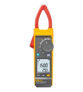
The Fluke 393 FC CAT III 1500 V True-rms Solar Clamp Meter with iFlex is designed for solar photovoltaic (PV) installation technicians and maintenance professionals who work in high voltage DC environments: PV arrays, wind power, electric railways, data centers battery banks for uninterruptible power supplies. The clamp meter will measure up to 1500 V DC and 1000 V AC with test leads, and up to 999.9 A DC or AC through the clamp jaw. The included iFlex flexible current probe extends AC current measurements up to 2500 A. The 393 has a thin jaw, giving you access to cables in crowded combiner boxes. Plus, the test leads are designed with your work in mind, and are also rated to CAT III 1500 V DC.
Key functions of the solar clamp meter:
- IP54 rated, ideal for work outdoors including PV panel testing
- DC power measurement, showing readings in kVA
- Audio Polarity indicator helps prevent accidental miswires
- Visual Continuity provides a bright green light in the display, ideal when working in dark and noisy environments
- Logging and reporting of test results via Fluke Connect software
- When measuring ac current the included iFlex flexible current probe gives you unparalleled access to cable is tight spaces. The iFlex probe can be twisted through extremely small spaces and provide accurate current measurements.
The world's first CAT III 1500 V true-RMS solar clamp meter
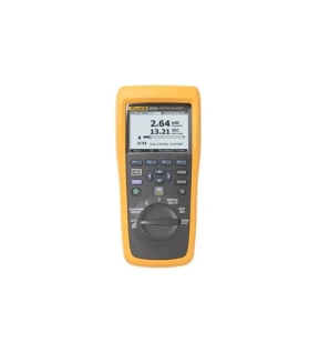
Reduced testing complexity, a simplified workflow and an intuitive user interface provide a new level of ease-of-use in battery testing.
• The ideal test tool for maintenance, troubleshooting and performance testing of individual stationary batteries and battery banks used in critical battery back-up applications
• The intuitive user interface, compact design and rugged construction ensure optimum performance, test results and reliability
• Covers a broad range of battery test functions ranging from DC voltage and resistance tests to full condition testing using automated string function testing and the test probe integrated infra-red temperature measurement system
• Designed for measurements on stationary batteries of all types.
Fluke BT510 key features:
• Battery Voltage – During the internal resistance test, Fluke Battery Analyzers also measure the voltage of the battery under test
• Discharge Volts – The Discharge mode collects the voltage of each battery multiple times at a user defined interval during a discharge or load test. Users can calculate the time a battery takes to drop to the cut-off voltage and use this time to determine the capacity loss of the battery
• Ripple Voltage Test – Measures unwanted residual ac component of the rectified voltage in dc charging and inverter circuits. Allows users to test ac components in dc charging circuits and find one of the root causes of battery deterioration
• Meter and Sequence Modes – The Meter mode is used for a quick test or troubleshooting. In this mode you can save and read the readings in a measurement or time sequence. The Sequence mode is for maintenance tasks with multiple power systems and battery strings. Before a task starts, users can configure a profile for the task for data management and report generation
• Threshold and Warning – Users can configure a maximum of 10 sets of thresholds and receive a Pass/ Warning/ Fail indication after each measurement
• Intercell Strap Resistance Test and Data Management – Measures the resistance of the intercell connection between batteries in a string.
• AutoHold – When AutoHold is turned on, a reading is captured when it remains stable for 1 second. The reading is then released when a new measurement starts
• AutoSave – When AutoSave is turned on, measured values are saved to internal memory automatically after an AutoHold reading is captured
• Fluke Battery Management Software – Easily import data from the Product to a PC. The measurement data and battery profile information is stored and archived with the Management Software and can be used for comparison and trend analysis. All measurement data, battery profile and analysis information can be used to easily generate reports
• Comprehensive logging – All measured values are automatically captured during testing and can be reviewed on the instrument before downloading for on the-go analysis
• Optimized user interface – Quick, guided setup ensures you're capturing the right data every time
• Battery life – 7.4 V 3000 mAh lithium-ion battery for more than eight hours continuous operation.
• USB port – For fast data download to supplied data analysis and report management application software.
• Highest safety rating in the industry – CAT III 600 V, 1000 V dc max. rated for safe measurements all around the battery power supply equipment.
Fluke BT520 Key features:
(Designed for measuring batteries in cabinets and hard to reach places)
• All of the above plus
• BTL20 Intelligent Test Probe set, with long and short probe extenders and built-in LCD display and speaker for visual and audio feedback
• BTL20ANG Intelligent Test Probe Set, with long and short angled tip probe extenders (no temperature sensor)
• Large soft carry case
Key Features
The ideal test tool for maintenance, troubleshooting and performance testing of individual stationary batteries and battery banks used in critical battery back-up applications
• Key measurements – Internal battery resistance, dc and ac voltage, dc and ac current, ripple voltage, frequency and temperature.
• Sequence measurement mode – Automatic or manual sequence testing of battery strings with automatic measurement storage including voltage, resistance and temperature (with BTL21 intelligent test probe), eliminating the need to press a button each time a measurement needs to be saved.
• Comprehensive logging – All measured values are automatically captured during testing and can be reviewed on the instrument before downloading for on the-go analysis.