Measuring Tools
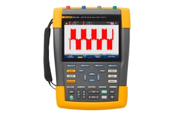
Fluke MDA-550 Series III Motor Drive Analyzer
Simplify complex motor drive troubleshooting with guided test setups and automatic drive measurement that provide reliable, repeatable test results.
The Fluke MDA 550 Motor-Drive Analyzer saves time and the hassle of setting up complex measurements, and simplifies the troubleshooting process. Simply select a step-by-step guided test and measurement will show you where to make voltage and current connections, while preset measurement profiles ensure you will get all the data you need for every critical motor drive part, from input to output, the DC bus, and the motor itself . Doing simple to complex measurements? MDA-550 can do it. What's more, making reports before (as-found) and after (as-left) repairs or adjustments becomes more practical. This is all thanks to its built-in report generator feature.
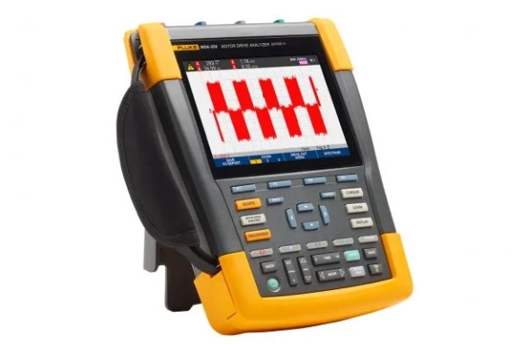
The MDA-550 is an ideal portable motor drive analysis testing tool. Not only that, this tool can also be used to safely detect and solve common problems in inverter-type motor drive systems.
- Measures main motor drive parameters , including voltage, current, DC bus voltage level and AC ripple, voltage and current unbalance and harmonics, voltage modulation, and motor shaft voltage discharge.
- Performs broader harmonic measurements to identify the impact of low and high order harmonics on your power system.
- Performs guided measurements of motor drive input, DC bus, drive output, motor input, and shaft measurements with step-by-step graphical diagrams of voltage and current connections.
- Uses simple measurement settings with preset measurement profiles to automatically trigger data collection based on the selected test procedure.
- Quickly and easily generate reports that are perfect for documenting problem solving and collaborative work with others.
- Measure additional electrical parameters with a complete 500 MHz oscilloscope, meter and logger capability for a wide range of electrical and electronic measurements in industrial systems
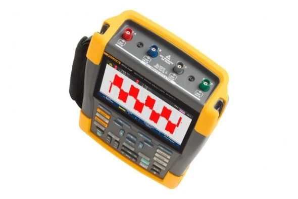
The Fluke MDA-550 Motor Drive Analyzer uses guided test measurements to make analysis even easier
Drive input
Quickly measure input voltage and current to see if values ??are within acceptable limits by comparing the rated voltage to the actual supply voltage. It then checks the input current to determine if the current is within its maximum rating and the conductor size is appropriate. You can also check if the harmonic distortion is within an acceptable level. There are two options for doing this: carefully examine the shape of the waveform or look at the harmonics spectrum screen which displays total harmonic distortion and individual harmonics.
Imbalance of voltage and current
Check the voltage unbalance at the input terminals so you can make sure the voltage unbalance is not too high (> 6-8%), and the phase rotation is correct. You can also check for current unbalance, as too large an imbalance can indicate a driving rectifier problem.
Wider harmonic measurement
Excess harmonics are not only a threat to your rotating machine, but also to other equipment connected to the mains power system. As well as being able to detect motor drive harmonics, the MDA-550 can also detect the potential impact of inverter switching electronics. The MDA-550 has three harmonic ranges, 1st to 51st harmonics, 1 to 9 kHz, and 9 kHz to 150 kHz providing the ability to detect harmonic pollution problems.
Bus DC
In motor drives, the conversion of AC to DC inside the drive is very important. The reason is that for the best drive performance it is necessary to have the right voltage and adequate smoothing with low ripple. High ripple voltages can be an indicator of a faulty capacitor or a faulty motor connected. The logging function can be used to dynamically check the performance of the DC bus in operating mode when load is applied.
Drive output
Check drive output focusing on voltage to frequency (V/F) ratio, and voltage modulation. If the V/F ratio is high, the motor may overheat. With a low V/F ratio, the connected motor may not be able to provide the torque required at the load to carry out the process for which it is intended.
Voltage modulation
Pulse Width Modulation signal measurements are used to check for high voltage peaks that can damage motor winding insulation. The rise time or steepness of the impulse is indicated by a dV/dt reading (value of change in voltage over time), this must be compared with the specified motor insulation. Metering can also be used to measure switching frequency. Its purpose is to detect whether there is a potential problem with the switching electronics, or with grounding, as the signal drifts up and down.
Input Motor
Ensuring the supply of voltage at the motor input terminal is important. However, choosing a connecting cable between the drive and the motor is no less important. Incorrect cable selection can cause damage to the drive and motor due to overvoltage peaks. Checking that the current at the terminals is within the motor's rating is critical because excess current can cause the motor to overheat, reducing the life of the stator insulation which can cause premature failure of the motor.
Motor shaft voltage
The voltage impulse in the variable speed drive is generated from the circuit between the motor stator and the rotor until a voltage appears on the rotor shaft. If the rotor shaft voltage exceeds the insulating capacity of the bearing grease, flashover currents (glow) may occur. As a result, pitting and fluting of the motor bearing rotation occurs, namely damage that causes the motor to fail prematurely. The MDA-550 is equipped with a carbon fiber brushed probe tip that makes it easy for you to detect destructive flashover currents. Meanwhile, the amplitude of the impulse and the number of events can be used as a consideration in taking preventive action. With the addition of these accessories and capabilities, you can spot potential faults without the need to buy expensive permanent solutions.
Step-by-step guided measurements ensure you have the data you need, when you need it
The MDA-550 is designed to help you quickly and easily test and troubleshoot common three-phase and single-phase inverter-type motor drive systems. Onscreen information and a step-by-step setup guide make it easy for you to configure the analyzer. Not only that, the information and guide will also provide the required drive measurements. That way, you can quickly make informed decisions regarding maintenance. From power input to attached motor, the MDA-550 provides measurement capabilities for the fastest motor drive solutions.
The Fluke MDA 550 Motor-Drive Analyzer saves time and the hassle of setting up complex measurements, and simplifies the troubleshooting process. Simply select a step-by-step guided test and measurement will show you where to make voltage and current connections, while preset measurement profiles ensure you will get all the data you need for every critical motor drive part, from input to output, the DC bus, and the motor itself . Doing simple to complex measurements? MDA-550 can do it. What's more, making reports before (as-found) and after (as-left) repairs or adjustments becomes more practical. This is all thanks to its built-in report generator feature.
The MDA-550 is an ideal portable motor drive analysis testing tool. Not only that, this tool can also be used to safely detect and solve common problems in inverter-type motor drive systems.
- Measures main motor drive parameters , including voltage, current, DC bus voltage level and AC ripple, voltage and current unbalance and harmonics, voltage modulation, and motor shaft voltage discharge.
- Performs broader harmonic measurements to identify the impact of low and high order harmonics on your power system.
- Performs guided measurements of motor drive input, DC bus, drive output, motor input, and shaft measurements with step-by-step graphical diagrams of voltage and current connections.
- Uses simple measurement settings with preset measurement profiles to automatically trigger data collection based on the selected test procedure.
- Quickly and easily generate reports that are perfect for documenting problem solving and collaborative work with others.
- Measure additional electrical parameters with a complete 500 MHz oscilloscope, meter and logger capability for a wide range of electrical and electronic measurements in industrial systems
The Fluke MDA-550 Motor Drive Analyzer uses guided test measurements to make analysis even easier
Drive input
Quickly measure input voltage and current to see if values ??are within acceptable limits by comparing the rated voltage to the actual supply voltage. It then checks the input current to determine if the current is within its maximum rating and the conductor size is appropriate. You can also check if the harmonic distortion is within an acceptable level. There are two options for doing this: carefully examine the shape of the waveform or look at the harmonics spectrum screen which displays total harmonic distortion and individual harmonics.
Imbalance of voltage and current
Check the voltage unbalance at the input terminals so you can make sure the voltage unbalance is not too high (> 6-8%), and the phase rotation is correct. You can also check for current unbalance, as too large an imbalance can indicate a driving rectifier problem.
Wider harmonic measurement
Excess harmonics are not only a threat to your rotating machine, but also to other equipment connected to the mains power system. As well as being able to detect motor drive harmonics, the MDA-550 can also detect the potential impact of inverter switching electronics. The MDA-550 has three harmonic ranges, 1st to 51st harmonics, 1 to 9 kHz, and 9 kHz to 150 kHz providing the ability to detect harmonic pollution problems.
Bus DC
In motor drives, the conversion of AC to DC inside the drive is very important. The reason is that for the best drive performance it is necessary to have the right voltage and adequate smoothing with low ripple. High ripple voltages can be an indicator of a faulty capacitor or a faulty motor connected. The logging function can be used to dynamically check the performance of the DC bus in operating mode when load is applied.
Drive output
Check drive output focusing on voltage to frequency (V/F) ratio, and voltage modulation. If the V/F ratio is high, the motor may overheat. With a low V/F ratio, the connected motor may not be able to provide the torque required at the load to carry out the process for which it is intended.
Voltage modulation
Pulse Width Modulation signal measurements are used to check for high voltage peaks that can damage motor winding insulation. The rise time or steepness of the impulse is indicated by a dV/dt reading (value of change in voltage over time), this must be compared with the specified motor insulation. Metering can also be used to measure switching frequency. Its purpose is to detect whether there is a potential problem with the switching electronics, or with grounding, as the signal drifts up and down.
Input Motor
Ensuring the supply of voltage at the motor input terminal is important. However, choosing a connecting cable between the drive and the motor is no less important. Incorrect cable selection can cause damage to the drive and motor due to overvoltage peaks. Checking that the current at the terminals is within the motor's rating is critical because excess current can cause the motor to overheat, reducing the life of the stator insulation which can cause premature failure of the motor.
Motor shaft voltage
The voltage impulse in the variable speed drive is generated from the circuit between the motor stator and the rotor until a voltage appears on the rotor shaft. If the rotor shaft voltage exceeds the insulating capacity of the bearing grease, flashover currents (glow) may occur. As a result, pitting and fluting of the motor bearing rotation occurs, namely damage that causes the motor to fail prematurely. The MDA-550 is equipped with a carbon fiber brushed probe tip that makes it easy for you to detect destructive flashover currents. Meanwhile, the amplitude of the impulse and the number of events can be used as a consideration in taking preventive action. With the addition of these accessories and capabilities, you can spot potential faults without the need to buy expensive permanent solutions.
Step-by-step guided measurements ensure you have the data you need, when you need it
The MDA-550 is designed to help you quickly and easily test and troubleshoot common three-phase and single-phase inverter-type motor drive systems. Onscreen information and a step-by-step setup guide make it easy for you to configure the analyzer. Not only that, the information and guide will also provide the required drive measurements. That way, you can quickly make informed decisions regarding maintenance. From power input to attached motor, the MDA-550 provides measurement capabilities for the fastest motor drive solutions.
Download
Produk Lainnya
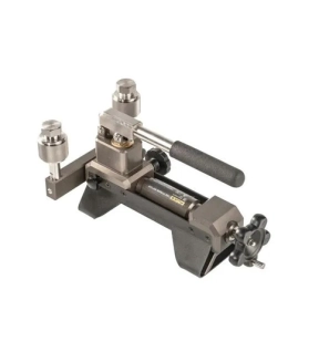
The New Fluke 730 series portable pumps feature fast pressure generation, stable pressure and easy-to-use. These pumps can provide stable, reliable pressure during calibration. The unique design of these pumps enables them to solve the common problems of pressure pump, such as blocking, leakage and laborious operation. They are your right-hand assistant in the process of manual pressure calibration.
In conjunction with Fluke 730G Smart Digital Pressure Calibrator with internal HART communication, these test pumps enable high-efficiency and high-accuracy measurement and calibration of pressure gauges, pressure switches, pressure transmitters, which make them ideal for metrology institutes and enterprises to establish pressure laboratories.
Key features
• Pressure range -95kPa to 600kPa
• Pressure is generated by the combination of the pressure rod and screw for faster and smoother pressure increase and decrease
• Safely switch between pressure and vacuum
• Two-year warranty. No worry to use.
• Special surface treatment, scratch and corrosion resistance.
• M20×1.5 female thread quick connection fitting
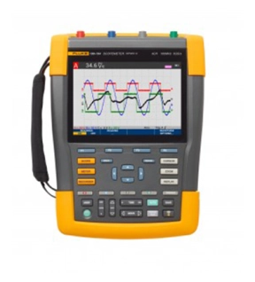
Fluke 190-104-III-S Offers
Accurate and versatile, this portable oscilloscope provides a fast sampling rate of up to 5 GS/s, a 200 ps resolution, and deep memory of 10,000 samples per channel. Perform timing or amplitude-related measurements on three phases or three-axis control systems, or compare and contrast multiple test points in a circuit under test.
- Up to four independent floating isolated inputs, up to 1000 V
- Up to 5 GS/s real time sampling (depending on model and channels used)
- Deep memory: 10,000 points per trace waveform capture (scope mode)
- CAT III 1000 V/CAT IV 600 V safety rated instrument for industrial environments
- Up to seven hours of battery operation using BP291
- Large, bright color display is easy to view in nearly any environment
- Easy to store and view historical data and transfer to a PC via USB or Wifi
- Convenient battery access door for quick battery swaps in the field
- IP51 rating, dust and drip-proof
- Connect-and-View triggering for intelligent, automatic triggering on fast, slow and even complex signals
- Frequency spectrum using FFT-analysis
- Automatic capture and REPLAY of 100 screens
- ScopeRecord mode gives 30,000 points per input channel for low frequency signal analysis
- TrendPlot Paperless Recorder mode with deep memory for longterm automatic measurements
- 5000 count DMM included in the 2-channel models
Applications
- Microelectronics
- Troubleshooting
Measure from mV to kV safely
Independently isolated inputs allow you to make measurements in mixed circuits having different ground references reducing the risk of accidental short circuits. Conventional bench oscilloscopes without special differential probes and isolation transformers can only reference measurements to line power earth ground. ScopeMeter 190 Series III test tools are engineered to cover a wide application range from mV to kV, so you’re ready for anything from microelectronics to heavy duty higher voltage electrical applications. 190 Series III 60 MHz and 100 MHz configurations include VPS421 100:1 probes for higher voltage applications, while the 200 MHz and 500 MHz configurations include VPS410-II 10:1 probes suitable for both microelectronics and higher voltage applications.
IP-51 rated for harsh environments
Rugged and shock-proof, ScopeMeter Test Tools are built for dirty, hazardous environments. With its sealed case, it can endure dust, drips, humidity and airborne pollutants. Every time you reach for ScopeMeter Test Tool you can be confident it will work reliably wherever your work takes you.
USB and Wi-Fi connectivity
The Fluke 190 Series III offers two USB ports, electrically isolated from measurement input circuits allowing you to quickly and easily transfer data to a PC, archive and share waveforms with OEMs, colleagues and support staff, or store waveforms, screen captures and instrument setups onto USB memory devices for later use. Easily transfer saved files via USB stick, direct connection via the USB interface or optional Wi-Fi connectivity. These files can be used for further data handling or in FlukeView-2 Software to study waveforms in greater detail.
Connect-and-View triggering
Connect-and-View triggering provides an instant, stable display without the need for adjusting settings. If you’ve used other scopes, you know how tricky triggering can be. If settings are incorrect, results can be unstable or incorrect. Connect-and-View automatically sets up correct triggering by recognizing signal patterns. Without touching a button, you get a stable, reliable and repeatable display of virtually any signal including motor drive and control signals. It’s especially fast and convenient when you’re measuring a number of test points in rapid succession.
Built-in digital multimeter
Conveniently switch from waveform analysis to precise multimeter measurements using the built in 5000 count digital multimeter on two channel 190 Series III models. Measurement functions include Vdc, Vac, Vac+dc, resistance, continuity and diode test. Measure current and temperature using suitable shunt, probe or adapter with wide range of scaling factors.
TrendPlot paperless recorder— records up to 11 days to help you find intermittent faults
The toughest faults to find are those that happen only once in a while. These intermittent events can be caused by bad connections, dust, dirt, corrosion, or simply broken wiring or connectors. Line outages, dips, swells and interruptions, or the starting and stopping of a motor can also cause a machine to stop. You may not be around when it happens, but the 190 Series III ScopeMeter Test Tool will be.
- Plot minimum and maximum peak values and average over time
- Plot any combination of up to four readings including voltages, amps, temperature, frequency and phase for all inputs, all with time and date stamp to pinpoint faults
When you invest in your Fluke test tools, you want your money to go as far as possible. Fluke Premium Care is a paid offering that provides coverage above and beyond the original product warranty, so you don’t need to worry about unexpected downtime caused by damaged test equipment, accessories, or tools in need of calibration or repair.
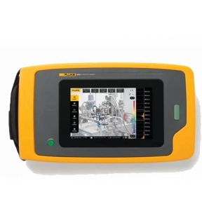
Fluke ii905 Acoustic Imager with LeakQ™: Detect, Locate, and Assess Gas Leaks
The Fluke ii905 Acoustic Imager equipped with LeakQ™ acoustic leak detection technology empowers maintenance teams to efficiently detect, locate, and assess gas and vacuum leaks. Whether you're dealing with compressed air systems, pipelines, or industrial equipment, the Fluke ii905 provides valuable insights to optimize your operations.
Key Features
• Ready-to-Use: The Fluke ii905 comes ready out of the box. Its rugged, ergonomic design ensures easy handling, while the large 7" LCD display provides clear leak visualization.
• Quick Detection: Even users with minimal experience can start detecting leaks within minutes. The tool estimates leak size and cost, incorporating a new distance-estimation feature and the 1-10 LeakQ™ severity index.
• SoundMap™ Overlay: The 7" LCD touchscreen overlays a SoundMap™ on visual images, facilitating rapid leak location identification.
• Intuitive Interface: Easily isolate leak sound frequencies and filter out background noise.
• Tagging and Organization: Use image and video tagging, annotation, and folders for efficient organization.
• Leak Sizing: Prioritize repairs based on leak size.
• Collaboration: The reporting tool allows seamless sharing of visuals, tagging, and notes with team members and repair personnel.
Money-Saving Insights:
Did you know that a 100 hp air compressor can consume around $50,000 in electricity annually? Shockingly, up to 30% of that electricity is wasted due to pressurizing airlines that leak. Many facilities overlook assessing the efficiency of their compressed air systems, leading to unnecessary capacity additions. The Fluke ii905 helps you identify leaks, optimize energy usage, and reduce costs.
LeakQ™ Mode:
Automatic Distance Estimation: When a leak is detected, the imager determines the distance to the target (indicated inside the circle on the display). The LeakQ value on the screen reflects the leak's size, based on measured dB SPL value and distance.
Comprehensive Reporting:
The LeakQ reporting tool combines data from your Fluke ii905 Acoustic Imager with direct inputs to create organized and detailed reports. These reports guide repairs, confirm fixes post-repair, and document the inspection process and results.
LeakQ online reporting tool
• Local PC installed application
• No Leak Type selection (should be included at the time of capturing the measurement)
• Offers customization of reporting template
Key features
• Easy, fast, and safe visual detection of compressed gas leaks with LeakQ™️ mode including estimated leak size and cost.
• The 7" LCD touchscreen overlays a SoundMap™️ on visual images, facilitating rapid leak location identification.
• The integrated visual- and textual tagging and annotation functionalities offer important details to optimize reporting and follow-up actions.
• On-the-go wireless upload to Fluke Connect
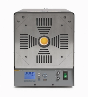
High performance furnace for thermocouple calibrations to 1200 °C
The Fluke Calibration 9118A Thermocouple Calibration Furnace is a horizontal, open-ended tube furnace with a temperature range of 300 °C to 1200 °C. It is used for comparison calibration of noble and base-metal thermocouples by secondary high-temperature labs and instrument shops in industries such as aerospace, automotive, energy, metals, and plastics. The 9118A is the most accurate, reliable, and flexible furnace in its class, meeting the demanding requirements of high-temperature thermocouple calibration.
The Fluke Calibration 9118A Thermocouple Calibration Furnace is a horizontal, open-ended tube furnace with a temperature range of 300 °C to 1200 °C. It is used for comparison calibration of noble and base-metal thermocouples by secondary high-temperature labs and instrument shops in industries such as aerospace, automotive, energy, metals, and plastics. The 9118A is the most accurate, reliable, and flexible furnace in its class, meeting the demanding requirements of high-temperature thermocouple calibration.