Measuring Tools
Fluke 9009 Industrial Dual-Block Thermometer Calibrator
Double your productivity or cut your calibration time in half
• Temperatures from –15 °C to 350 °C in one unit
• Two wells in each block for simultaneous comparison calibrations
• Rugged, lightweight, water-resistant enclosure
You’ve been asking for it and now we’re making it for you. The Model 9009 Industrial Dual-Block Calibrator lets you calibrate at hot and cold temperatures at the same time. Double your productivity or cut your calibration time in half—either way you look at it, your in-field temperature calibrations just got easier.
Download
Produk Lainnya
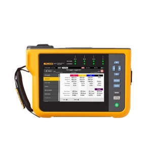
Automatic measurements. More flexibility. Better power quality troubleshooting.
Fluke 1770 Series Three-Phase Power Quality Analyzers eliminate the complexities of power quality logging, troubleshooting, and analysis. Engineered to be the faster, easier way to perform power quality studies, the 1770 Series offers automatic measurements, a straightforward user interface and setup, best-in-class specifications, and a simplified reporting platform. The instrument can also be powered directly from the measurement circuit, eliminating the need to find a power outlet or use a lengthy extension cord.
With the 1770 Series you’ll never miss a critical power quality event—from fast transients up to 8 kV, harmonics up to 30 kHz, dips and swells, as well as the voltage, current, and power measurements that enable you to characterize your electrical system.
Automatic measurement capture
Whether you’re performing a quick system check or a detailed power quality study, consistent data is key. The Fluke 1770 Series offers a unique automatic measurement capture system that helps ensure you’re collecting the right data every time, while still giving you the flexibility to select and adjust specific parameters as needed. More than 500 power quality parameters are captured by default and the guided setup makes it easy to select the right parameters for the system you’re working on. Logged data is instantly viewable, downloadable, and shareable with Fluke Energy Analyze Plus software so you never need to wait to finish a session before reviewing results or analyzing data.
Ultimate measurement confidence
The Fluke 1770 Series are 2-in-1 devices that combine the troubleshooting functionality of a power quality meter with the robust analysis and logging capabilities of a standalone power quality analyzer—in a single, easy-to-use, handheld device.
The ‘PQ Meter’ function gives you immediate access to live onscreen data in the field so you can quickly identify potential problems while troubleshooting. The detailed ‘PQ Logging and Analysis’ function eliminates the complexity of performing power quality studies by guiding you through the setup process ensuring you’re capturing the right data every time. Couple these measurement modes with a unique measurement connection autocorrect function and you can be confident that you never need to worry about going back for a second measurement—even if you were unsure about what to look for when you started.
Powerful analysis software with easy-to-create reports
Fluke 1770 Series Power Quality Analyzers come standard with the powerful Fluke Energy Analyze Plus software, designed to eliminate the hassles found with other multi-purpose application software. Energy Analyze Plus helps you evaluate power quality data right out of the box and without extensive training.
Energy Analyze Plus makes downloading, analyzing, tracking, and reporting power quality and energy data easier than ever. Quickly compare results to historical values, benchmark against industry norms, compare measured data to local conditions, and create a more complete picture of what’s occurring across your facility, even as the data is still being collected. Energy Analyze Plus offers unified support for the Fluke 1730, 1740, and 1770 Series of Energy Loggers and Power Quality Analyzers.
“In-workshop” and “in-the-field” setup and download through PC application software
Simple data downloads using USB memory stick, WiFi, LTE, wired Ethernet, or USB cable
Analyze every measured detail of energy consumption and power quality state-of-health with automated reporting
One-touch reporting creates standardized reports conforming to standards like EN 50160, IEEE 519, GOST 33073 IEC 61000-2-2, or export data in PQDIF or NeQual compatible format or CSV for use with third-party software
Advanced analysis allows the user to choose any available logged parameter and create a highly customized view of measurements for advanced data correlation
High-speed voltage transient capture
Transients negatively impact otherwise healthy systems every day and their potential to damage your equipment can’t be underestimated. Whether your system is experiencing impulsive or oscillatory transients, the results can be devastating and cause problems ranging from insulation failures to total equipment failures. The Fluke 1775 and Fluke 1777 incorporate advanced transient capture technology to help you clearly identify high-speed voltage transients, so you have the data you need to stop them in their tracks. The Fluke 1775 Power Quality Analyzer has 1MHz sampling capability to capture fast transients, while the Fluke 1777 Power Quality Analyzer has 20MHz sampling capability to capture the fastest transients in high detail.
Compliant to international standards
The Fluke 1770 Series offers the best-in-class accuracy you’ve come to expect from a Fluke Power Quality Analyzer in a future IEC 61000-4-30 Class A edition 3 compliant package. On top of that, the 1770 Series has been engineered to meet the future requirements of Class A edition, for conformance to EN 50160 and IEEE 519, so you’ll be prepared to tackle tomorrow’s measurement requirements, today.
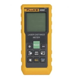
- Quickly measure distance, calculate area / volume / pythagoras
- Auto level and height
- Built to withstand rainy or dusty conditions: 1-meter drop tested with rated IP54 (Fluke 404E / 406E), IP65 (Fluke 405 / 408 / 410),
- Electronic angle display, auxiliary level measurement
- Up to 100 sets of data storage
- The battery life up to 5000 single measurements Automatically power off after 3 minutes of inactivity
Fluke 405 / 408 / 410 provide additional features as :
- Universal tripod interface, easy to use
- Type-C charging port, strong endurance
- 2-inch HD display, clear viewing in full sunlight
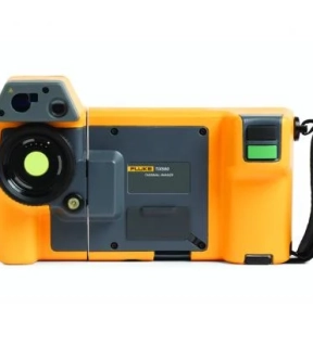
Bring out the best for work.
The Ti580 is a rugged and superbly built 640 x 480 thermal image camera. Now users can perform thermal image checks more confidently and faster than ever before - all thanks to the ruggedness and ease of use that Fluke has come to expect.
See sharper and clearer images for more accurate interpretation.
A screen that can rotate 240 degrees makes it easier to take pictures when the equipment is in an area that is difficult or not easy to reach. The ergonomic design and neck strap make long inspection days easier. Outdoors, the swivel display lets you adjust it to minimize glare, and the Fluke 5.7" touchscreen LCD offers premium viewing in the field - truly "built for a purpose."
Includes new, powerful and easy-to-use Fluke Connect® SmartView® desktop software.
The Fluke Connect SmartView desktop software is a comprehensive and connected software platform that represents the future of integrated equipment maintenance, monitoring, analysis and reporting now available. It's easier than ever to optimize thermal analysis, generate fast, customizable and powerful reports and export images to your preferred format in the cloud. And you'll be able to integrate it with Fluke Connect – the world's largest system of integrated maintenance tools and software.
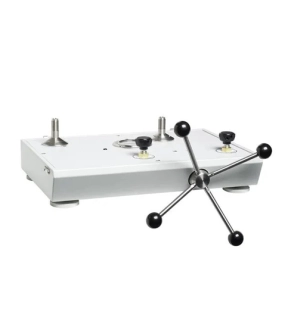
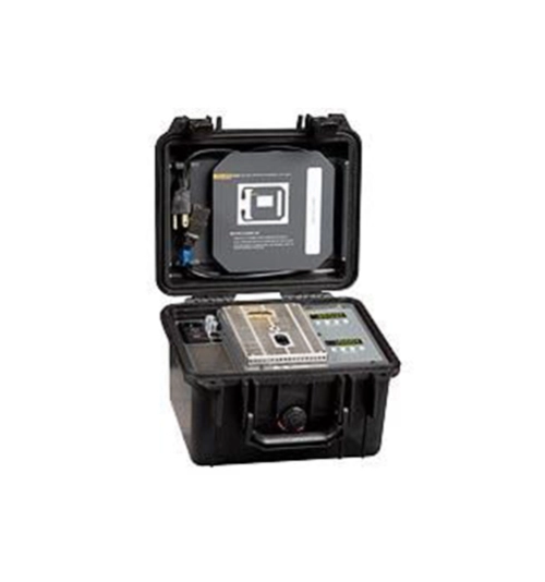
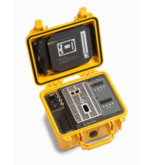
This pneumatic comparison test pump is designed for testing pressure measuring instruments against master test instruments. This cost effective instrument provides precise control for important calibration requirements and include many features found in our popular line of pneumatic deadweight testers.
*Note --- Unit requires pressure source (i.e. nitrogen bottle) for operation.
Key Features
• High pressure pneumatic operation
• Screw press for fine pressure adjustments
• High quality needle valves for fine control
• Test port adapters which require no PTFE tape or wrenches
• Sturdy carrying case with lid