Measuring Tools
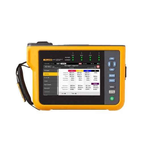
Fluke 1777 - Three-Phase Power Quality Analyzer
Automatic measurements. More flexibility. Better power quality troubleshooting.
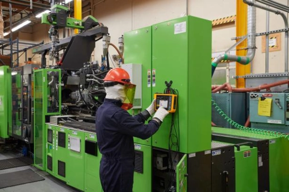
Fluke 1770 Series Three-Phase Power Quality Analyzers eliminate the complexities of power quality logging, troubleshooting, and analysis. Engineered to be the faster, easier way to perform power quality studies, the 1770 Series offers automatic measurements, a straightforward user interface and setup, best-in-class specifications, and a simplified reporting platform. The instrument can also be powered directly from the measurement circuit, eliminating the need to find a power outlet or use a lengthy extension cord.
With the 1770 Series you’ll never miss a critical power quality event—from fast transients up to 8 kV, harmonics up to 30 kHz, dips and swells, as well as the voltage, current, and power measurements that enable you to characterize your electrical system.
Automatic measurement capture
Whether you’re performing a quick system check or a detailed power quality study, consistent data is key. The Fluke 1770 Series offers a unique automatic measurement capture system that helps ensure you’re collecting the right data every time, while still giving you the flexibility to select and adjust specific parameters as needed. More than 500 power quality parameters are captured by default and the guided setup makes it easy to select the right parameters for the system you’re working on. Logged data is instantly viewable, downloadable, and shareable with Fluke Energy Analyze Plus software so you never need to wait to finish a session before reviewing results or analyzing data.
Ultimate measurement confidence
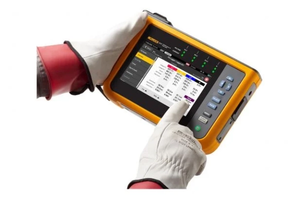
The Fluke 1770 Series are 2-in-1 devices that combine the troubleshooting functionality of a power quality meter with the robust analysis and logging capabilities of a standalone power quality analyzer—in a single, easy-to-use, handheld device.
The ‘PQ Meter’ function gives you immediate access to live onscreen data in the field so you can quickly identify potential problems while troubleshooting. The detailed ‘PQ Logging and Analysis’ function eliminates the complexity of performing power quality studies by guiding you through the setup process ensuring you’re capturing the right data every time. Couple these measurement modes with a unique measurement connection autocorrect function and you can be confident that you never need to worry about going back for a second measurement—even if you were unsure about what to look for when you started.
Powerful analysis software with easy-to-create reports
Fluke 1770 Series Power Quality Analyzers come standard with the powerful Fluke Energy Analyze Plus software, designed to eliminate the hassles found with other multi-purpose application software. Energy Analyze Plus helps you evaluate power quality data right out of the box and without extensive training.
Energy Analyze Plus makes downloading, analyzing, tracking, and reporting power quality and energy data easier than ever. Quickly compare results to historical values, benchmark against industry norms, compare measured data to local conditions, and create a more complete picture of what’s occurring across your facility, even as the data is still being collected. Energy Analyze Plus offers unified support for the Fluke 1730, 1740, and 1770 Series of Energy Loggers and Power Quality Analyzers.
“In-workshop” and “in-the-field” setup and download through PC application software
Simple data downloads using USB memory stick, WiFi, LTE, wired Ethernet, or USB cable
Analyze every measured detail of energy consumption and power quality state-of-health with automated reporting
One-touch reporting creates standardized reports conforming to standards like EN 50160, IEEE 519, GOST 33073 IEC 61000-2-2, or export data in PQDIF or NeQual compatible format or CSV for use with third-party software
Advanced analysis allows the user to choose any available logged parameter and create a highly customized view of measurements for advanced data correlation
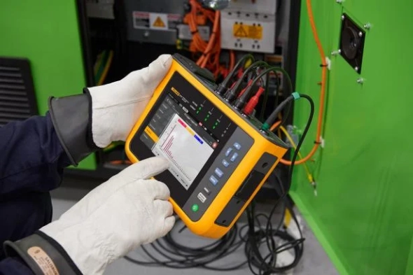
High-speed voltage transient capture
Transients negatively impact otherwise healthy systems every day and their potential to damage your equipment can’t be underestimated. Whether your system is experiencing impulsive or oscillatory transients, the results can be devastating and cause problems ranging from insulation failures to total equipment failures. The Fluke 1775 and Fluke 1777 incorporate advanced transient capture technology to help you clearly identify high-speed voltage transients, so you have the data you need to stop them in their tracks. The Fluke 1775 Power Quality Analyzer has 1MHz sampling capability to capture fast transients, while the Fluke 1777 Power Quality Analyzer has 20MHz sampling capability to capture the fastest transients in high detail.
Compliant to international standards
The Fluke 1770 Series offers the best-in-class accuracy you’ve come to expect from a Fluke Power Quality Analyzer in a future IEC 61000-4-30 Class A edition 3 compliant package. On top of that, the 1770 Series has been engineered to meet the future requirements of Class A edition, for conformance to EN 50160 and IEEE 519, so you’ll be prepared to tackle tomorrow’s measurement requirements, today.
Fluke 1770 Series Three-Phase Power Quality Analyzers eliminate the complexities of power quality logging, troubleshooting, and analysis. Engineered to be the faster, easier way to perform power quality studies, the 1770 Series offers automatic measurements, a straightforward user interface and setup, best-in-class specifications, and a simplified reporting platform. The instrument can also be powered directly from the measurement circuit, eliminating the need to find a power outlet or use a lengthy extension cord.
With the 1770 Series you’ll never miss a critical power quality event—from fast transients up to 8 kV, harmonics up to 30 kHz, dips and swells, as well as the voltage, current, and power measurements that enable you to characterize your electrical system.
Automatic measurement capture
Whether you’re performing a quick system check or a detailed power quality study, consistent data is key. The Fluke 1770 Series offers a unique automatic measurement capture system that helps ensure you’re collecting the right data every time, while still giving you the flexibility to select and adjust specific parameters as needed. More than 500 power quality parameters are captured by default and the guided setup makes it easy to select the right parameters for the system you’re working on. Logged data is instantly viewable, downloadable, and shareable with Fluke Energy Analyze Plus software so you never need to wait to finish a session before reviewing results or analyzing data.
Ultimate measurement confidence
The Fluke 1770 Series are 2-in-1 devices that combine the troubleshooting functionality of a power quality meter with the robust analysis and logging capabilities of a standalone power quality analyzer—in a single, easy-to-use, handheld device.
The ‘PQ Meter’ function gives you immediate access to live onscreen data in the field so you can quickly identify potential problems while troubleshooting. The detailed ‘PQ Logging and Analysis’ function eliminates the complexity of performing power quality studies by guiding you through the setup process ensuring you’re capturing the right data every time. Couple these measurement modes with a unique measurement connection autocorrect function and you can be confident that you never need to worry about going back for a second measurement—even if you were unsure about what to look for when you started.
Powerful analysis software with easy-to-create reports
Fluke 1770 Series Power Quality Analyzers come standard with the powerful Fluke Energy Analyze Plus software, designed to eliminate the hassles found with other multi-purpose application software. Energy Analyze Plus helps you evaluate power quality data right out of the box and without extensive training.
Energy Analyze Plus makes downloading, analyzing, tracking, and reporting power quality and energy data easier than ever. Quickly compare results to historical values, benchmark against industry norms, compare measured data to local conditions, and create a more complete picture of what’s occurring across your facility, even as the data is still being collected. Energy Analyze Plus offers unified support for the Fluke 1730, 1740, and 1770 Series of Energy Loggers and Power Quality Analyzers.
“In-workshop” and “in-the-field” setup and download through PC application software
Simple data downloads using USB memory stick, WiFi, LTE, wired Ethernet, or USB cable
Analyze every measured detail of energy consumption and power quality state-of-health with automated reporting
One-touch reporting creates standardized reports conforming to standards like EN 50160, IEEE 519, GOST 33073 IEC 61000-2-2, or export data in PQDIF or NeQual compatible format or CSV for use with third-party software
Advanced analysis allows the user to choose any available logged parameter and create a highly customized view of measurements for advanced data correlation
High-speed voltage transient capture
Transients negatively impact otherwise healthy systems every day and their potential to damage your equipment can’t be underestimated. Whether your system is experiencing impulsive or oscillatory transients, the results can be devastating and cause problems ranging from insulation failures to total equipment failures. The Fluke 1775 and Fluke 1777 incorporate advanced transient capture technology to help you clearly identify high-speed voltage transients, so you have the data you need to stop them in their tracks. The Fluke 1775 Power Quality Analyzer has 1MHz sampling capability to capture fast transients, while the Fluke 1777 Power Quality Analyzer has 20MHz sampling capability to capture the fastest transients in high detail.
Compliant to international standards
The Fluke 1770 Series offers the best-in-class accuracy you’ve come to expect from a Fluke Power Quality Analyzer in a future IEC 61000-4-30 Class A edition 3 compliant package. On top of that, the 1770 Series has been engineered to meet the future requirements of Class A edition, for conformance to EN 50160 and IEEE 519, so you’ll be prepared to tackle tomorrow’s measurement requirements, today.
Download
Products Lainnya
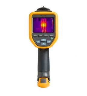
Save time with precise infrared levels and analysis
Whether you're on the roof checking heating, ventilation and air conditioning, deep in the factory checking motors, or if you've locked down the electrical panels, you rely on a tool that has the power and features to do the job quickly.
The Fluke TiS20+ and TiS20+ MAX handheld thermal cameras put the power of thermal imaging at your fingertips. Designed to make your job faster and easier, this thermal imager is the perfect tool for:
- Commercial electrician
- Heating, ventilation, air conditioning and refrigeration technician
- Maintenance technician
Get context with a combination of visual light and infrared images
In thermography, context is important. Let Fluke IR-Fusion™ make your job easier by using a thermal image superimposed on a visual light image to provide a complete picture of where an issue is a problem before it actually becomes a problem. Just slide your finger across the screen to adjust the infrared level. Whether you're experiencing an uneven load on your switchgear or checking your ventilation system, the Fluke TiS20+ helps you quickly detect issues.
You work hard all day, your tools too
You must not let your thermal imager be damaged by the environment. You can sleep well at night knowing that your camera will stand up to whatever the day throws at it.
- 2 meter high drop test
- Waterproof (IP54)
- Dustproof (IP54)
Stop sorting, start analyzing with Fluke Connect Asset Tagging
Avoid long hours on the computer setting up your thermal images, let Asset Tagging do all the work for you. No more dragging and dropping or renaming files in the office, just scan the QR code on your assets, take thermal images and they are automatically sorted by assets. Start spending your time analyzing images and creating reports instead of sorting files one by one.
Longest battery life in a Fluke thermal camera
The TiS20+ and TiS20+ MAX work non-stop, with a battery life of over 5 hours of continuous use making it the longest battery life in a Fluke thermal camera. Save battery power for multiple inspection points with sleep mode. Just press the power button once and you are ready to go.

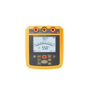
The Fluke 1535 and 1537 2,500 V Insulation Resistance Testers are engineered to simplify frontline troubleshooting whether you’re on the factory floor or working in the field at a solar installation. With user selectable test voltages from 250 V to 2,500 V and resistance measurements up to 500 GΩ these testers allow you to cover more workload with a single tool. Equipped with an intuitive user interface, a short circuit current of up to 5 mA and a CAT IV 600 V rating these portable high-voltage insulation testers can deliver rapid and stable resistance measurements no matter where you take them. The 1537 Insulation Resistance Tester also allows you to store measurements for later review or PC transfer, using the provided software.
• Selectable Voltage Tests: Tailor your tests with user-selectable voltages of 250 V, 500 V, 1000 V, and 2500 V to cover both industrial and solar applications.
• Extended Insulation Resistance Measurement: Reach up to 500 GΩ in insulation resistance measurement for a thorough analysis.
• Intelligent Calculations: Automatically calculate Polarization Index (PI) and Dielectric Absorption Ratio (DAR), minimizing the influence of environmental factors.
• High Measurement Capacity: Execute up to 1,300 measurements at 2,500 V or 6,500 measurements at 250 V on a single charge, enhancing productivity.
• Enhanced Safety Features: Benefit from a CAT IV 600V rating and a built-in voltage alarm function for heightened safety during operations.
The Fluke 1537 has these additional features:
• Extended Measurements: The Fluke 1537 enhances your testing capabilities with AC/DC voltage and resistance measurements.
• Stable Resistance Measurements: Achieve faster, more stable insulation resistance measurements with a short circuit current up to 5mA.
• Fine-tunable Test Voltage: Adjust the test voltage from 250 V to 2500 V in 100 V increments to meet specific testing requirements.
• Dielectric Discharge Rate Calculation: Automatically calculate the dielectric discharge rate (DD) to aid in identifying elusive insulation issues.
• Ramp Test Mode: Linearly increase the applied test voltage 100 V/s to help identify potentially hard to identify fault conditions.
• Visual and Audio Continuity Indicator: Verify continuity visually on the screen display or with the audible indicator so you can focus on your testing procedure without looking at the display.
• Customizable Testing Parameters: Set user-defined labels, adjust test duration, and store measurement results for a tailored testing experience.
• Effortless Data Management: Download and manage data effortlessly with the provided PC software.
• Extended Warranty: Enjoy peace of mind with an extended 3-year warranty.
Key Features
• User-selectable voltages of 250 V-2500 V
• Up to 500 GΩ insulation resistance measurement
• Short circuit current up to 5mA for fast, stable measurements
• Automatically calculate PI and DAR
• Perform 1,300+ insulation tests on a single charge
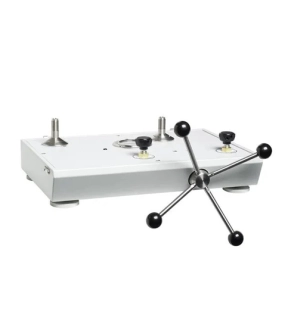
This pneumatic comparison test pump is designed for testing pressure measuring instruments against master test instruments. This cost effective instrument provides precise control for important calibration requirements and include many features found in our popular line of pneumatic deadweight testers.
*Note --- Unit requires pressure source (i.e. nitrogen bottle) for operation.
Key Features
• High pressure pneumatic operation
• Screw press for fine pressure adjustments
• High quality needle valves for fine control
• Test port adapters which require no PTFE tape or wrenches
• Sturdy carrying case with lid