Measuring Tools
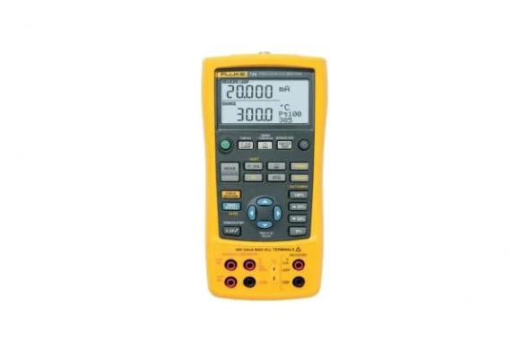
Fluke 726 Precision Multifunction Calibrators
Process calibration designed specifically for process industries
The Fluke 726 is a precise and powerful, yet easy-to-use, field calibrator. It features broad workload coverage, calibration power, and unsurpassed accuracy needed by process professionals. It measures and sources almost all process parameters to calibrate almost anything. Use it to test sensors and valves, and to test and calibrate transmitters. The 726 interprets results without the help of a calculator and stores measurement data for later analysis.
Measurement capabilities
This precision multifunction calibrator measures volts, mA, pressure, RTDs, thermocouples, frequency, and resistance to test sensors and transmitters. The 726 also sources and simulates volts, mA, thermocouples, RTDs, frequency to calibrate transmitters. Measures and/or sources pressure using when paired with any of the 50 Fluke 750P series Pressure Modules to test and calibrate pressure transmitters and other devices. The 726 can also:
- Source mA with simultaneous pressure measurement to conduct valve and I/P test
- Conduct enhanced flowmeter testing with frequency totalizer and frequency pulse train source mode
Designed for ease of use
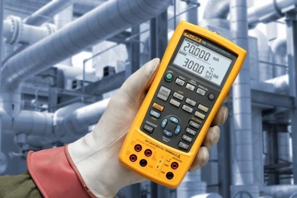
The 726 has built-in features that make it easier to use in nearly any measurement situation. From its ability to store frequently used test setups, to programming custom RTD probe calibration constants for enhanced temperature measurement, or the integrated voltage input protection design that improves reliability, the 726 is built to perform. The use of two separate channels even allows you to measure, source, or view process signals simultaneously. The backlit display provides better visibility in low-light conditions, and the standard 3-year warranty provides extra confidence that the 726 will be there when you need it to be.
You can also use the 726 to:
- Capture the set, reset, and deadband of a pressure switch with the integrated switch test
- Calculate the transmitter error % to interpret calibration results without the use of a calculator
- Perform fast linearity tests with the auto-step and auto-ramp features
- Power a transmitter during test using 24 V loop supply and simultaneous mA measurement
The Fluke 726 is a precise and powerful, yet easy-to-use, field calibrator. It features broad workload coverage, calibration power, and unsurpassed accuracy needed by process professionals. It measures and sources almost all process parameters to calibrate almost anything. Use it to test sensors and valves, and to test and calibrate transmitters. The 726 interprets results without the help of a calculator and stores measurement data for later analysis.
Measurement capabilities
This precision multifunction calibrator measures volts, mA, pressure, RTDs, thermocouples, frequency, and resistance to test sensors and transmitters. The 726 also sources and simulates volts, mA, thermocouples, RTDs, frequency to calibrate transmitters. Measures and/or sources pressure using when paired with any of the 50 Fluke 750P series Pressure Modules to test and calibrate pressure transmitters and other devices. The 726 can also:
- Source mA with simultaneous pressure measurement to conduct valve and I/P test
- Conduct enhanced flowmeter testing with frequency totalizer and frequency pulse train source mode
Designed for ease of use
The 726 has built-in features that make it easier to use in nearly any measurement situation. From its ability to store frequently used test setups, to programming custom RTD probe calibration constants for enhanced temperature measurement, or the integrated voltage input protection design that improves reliability, the 726 is built to perform. The use of two separate channels even allows you to measure, source, or view process signals simultaneously. The backlit display provides better visibility in low-light conditions, and the standard 3-year warranty provides extra confidence that the 726 will be there when you need it to be.
You can also use the 726 to:
- Capture the set, reset, and deadband of a pressure switch with the integrated switch test
- Calculate the transmitter error % to interpret calibration results without the use of a calculator
- Perform fast linearity tests with the auto-step and auto-ramp features
- Power a transmitter during test using 24 V loop supply and simultaneous mA measurement
Download
Produk Lainnya
When you invest in your Fluke test tools, you want your money to go as far as possible. Fluke Premium Care is a paid offering that provides coverage above and beyond the original product warranty, so you don’t need to worry about unexpected downtime caused by damaged test equipment, accessories, or tools in need of calibration or repair.
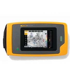
Fluke ii905 Acoustic Imager with LeakQ™: Detect, Locate, and Assess Gas Leaks
The Fluke ii905 Acoustic Imager equipped with LeakQ™ acoustic leak detection technology empowers maintenance teams to efficiently detect, locate, and assess gas and vacuum leaks. Whether you're dealing with compressed air systems, pipelines, or industrial equipment, the Fluke ii905 provides valuable insights to optimize your operations.
Key Features
• Ready-to-Use: The Fluke ii905 comes ready out of the box. Its rugged, ergonomic design ensures easy handling, while the large 7" LCD display provides clear leak visualization.
• Quick Detection: Even users with minimal experience can start detecting leaks within minutes. The tool estimates leak size and cost, incorporating a new distance-estimation feature and the 1-10 LeakQ™ severity index.
• SoundMap™ Overlay: The 7" LCD touchscreen overlays a SoundMap™ on visual images, facilitating rapid leak location identification.
• Intuitive Interface: Easily isolate leak sound frequencies and filter out background noise.
• Tagging and Organization: Use image and video tagging, annotation, and folders for efficient organization.
• Leak Sizing: Prioritize repairs based on leak size.
• Collaboration: The reporting tool allows seamless sharing of visuals, tagging, and notes with team members and repair personnel.
Money-Saving Insights:
Did you know that a 100 hp air compressor can consume around $50,000 in electricity annually? Shockingly, up to 30% of that electricity is wasted due to pressurizing airlines that leak. Many facilities overlook assessing the efficiency of their compressed air systems, leading to unnecessary capacity additions. The Fluke ii905 helps you identify leaks, optimize energy usage, and reduce costs.
LeakQ™ Mode:
Automatic Distance Estimation: When a leak is detected, the imager determines the distance to the target (indicated inside the circle on the display). The LeakQ value on the screen reflects the leak's size, based on measured dB SPL value and distance.
Comprehensive Reporting:
The LeakQ reporting tool combines data from your Fluke ii905 Acoustic Imager with direct inputs to create organized and detailed reports. These reports guide repairs, confirm fixes post-repair, and document the inspection process and results.
LeakQ online reporting tool
• Local PC installed application
• No Leak Type selection (should be included at the time of capturing the measurement)
• Offers customization of reporting template
Key features
• Easy, fast, and safe visual detection of compressed gas leaks with LeakQ™️ mode including estimated leak size and cost.
• The 7" LCD touchscreen overlays a SoundMap™️ on visual images, facilitating rapid leak location identification.
• The integrated visual- and textual tagging and annotation functionalities offer important details to optimize reporting and follow-up actions.
• On-the-go wireless upload to Fluke Connect
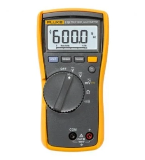
Compact true-rms meter for accurate electrical installation and troubleshooting
The Fluke 110 is a versatile multimeter for electrical measurements and troubleshooting. Trusted by residential and commercial electricians for troubleshooting and maintenance. The Fluke 110 is intended for professional use where true-rms accuracy is required.
Key product capabilities
- True-rms ac voltage for accurate measurements on non-linear signals
- Great white LED backlight for working in dark areas
- Resistance and continuity
- Min./Max./Average to record signal fluctuations
- CAT III 600 V safety rating
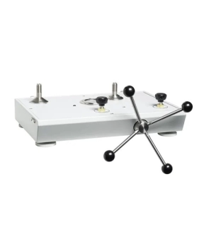
This pneumatic comparison test pump is designed for testing pressure measuring instruments against master test instruments. This cost effective instrument provides precise control for important calibration requirements and include many features found in our popular line of pneumatic deadweight testers.
*Note --- Unit requires pressure source (i.e. nitrogen bottle) for operation.
Key Features
• High pressure pneumatic operation
• Screw press for fine pressure adjustments
• High quality needle valves for fine control
• Test port adapters which require no PTFE tape or wrenches
• Sturdy carrying case with lid
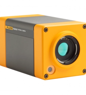
When it's not just infrared.
Introducing Fluke infrared cameras, the first with full radiometry technology – the RSE series. Packed with advanced features and plug-in software for MATLAB® and LabVIEW® , these tools are ideal for continuous streaming and analysis of infrared data.
Designed for your research, science and engineering needs, enhance your testing and quality assurance procedures by attaching the RSE600 to your workstation. Continuously stream up to 60 frames per second of data directly to your computer to monitor minute temperature differences, as well as analyze remote video frame-by-frame from the SmartView® desktop software . Get an even more perfect screen with add-on lenses to target different applications (analyzing from a distance, or getting detailed close-ups).
Don't just look at the heat. Stream, measure and analyze its power as well.
With plug-ins for MATLAB® and LabVIEW® , the RSE Infrared Camera is perfect for testing and development. Looking for more robust software to monitor and archive processing manufacturing data 24/7? We recommend the ThermoView® series from Fluke Process Instruments. Check out a quick comparison