Measuring Tools
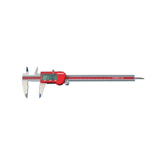
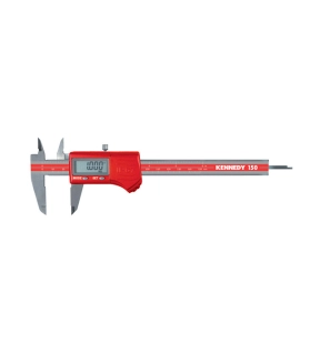
Kennedy 8"/200mm DIGITAL ABS ELECTRONIC CALIPER
Modern design with a knurled thumb wheel for easy use when taking internal and external depth and step measurements.
Dual readout giving instant inch/metric conversion at the touch of a button.
Zero reset at any point, large clear display, error-free operation, fast response speed. Non-output type.
Resolution: 0.01mm/0.0005".
Extra batteries available - Order Code EDI -904-4000K.
Dual readout giving instant inch/metric conversion at the touch of a button.
Zero reset at any point, large clear display, error-free operation, fast response speed. Non-output type.
Resolution: 0.01mm/0.0005".
Extra batteries available - Order Code EDI -904-4000K.
Download
Products Lainnya
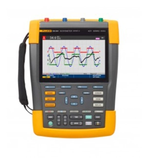
Fluke 190-504-III Offers
Accurate and versatile, this portable oscilloscope provides a fast sampling rate of up to 5 GS/s, a 200 ps resolution, and deep memory of 10,000 samples per channel. Perform timing or amplitude-related measurements on three phases or three-axis control systems, or compare and contrast multiple test points in a circuit under test
- Up to four independent floating isolated inputs, up to 1000 V
- Up to 5 GS/s real time sampling (depending on model and channels used)
- Deep memory: 10,000 points per trace waveform capture (scope mode)
- CAT III 1000 V/CAT IV 600 V safety rated instrument for industrial environments
- Up to seven hours of battery operation using BP291
- Large, bright color display is easy to view in nearly any environment
- Easy to store and view historical data and transfer to a PC via USB or Wifi
- Convenient battery access door for quick battery swaps in the field
- IP51 rating, dust and drip-proof
- Connect-and-View triggering for intelligent, automatic triggering on fast, slow and even complex signals
- Frequency spectrum using FFT-analysis
- Automatic capture and REPLAY of 100 screens
- ScopeRecord mode gives 30,000 points per input channel for low frequency signal analysis
- TrendPlot Paperless Recorder mode with deep memory for longterm automatic measurements
- 5000 count DMM included in the 2-channel models
Applications
- Microelectronics
- Troubleshooting
Measure from mV to kV safely
Independently isolated inputs allow you to make measurements in mixed circuits having different ground references reducing the risk of accidental short circuits. Conventional bench oscilloscopes without special differential probes and isolation transformers can only reference measurements to line power earth ground. ScopeMeter 190 Series III test tools are engineered to cover a wide application range from mV to kV, so you’re ready for anything from microelectronics to heavy duty higher voltage electrical applications. 190 Series III 60 MHz and 100 MHz configurations include VPS421 100:1 probes for higher voltage applications, while the 200 MHz and 500 MHz configurations include VPS410-II 10:1 probes suitable for both microelectronics and higher voltage applications.
IP-51 rated for harsh environments
Rugged and shock-proof, ScopeMeter Test Tools are built for dirty, hazardous environments. With its sealed case, it can endure dust, drips, humidity and airborne pollutants. Every time you reach for ScopeMeter Test Tool you can be confident it will work reliably wherever your work takes you.
USB and Wi-Fi connectivity
The Fluke 190 Series III offers two USB ports, electrically isolated from measurement input circuits allowing you to quickly and easily transfer data to a PC, archive and share waveforms with OEMs, colleagues and support staff, or store waveforms, screen captures and instrument setups onto USB memory devices for later use. Easily transfer saved files via USB stick, direct connection via the USB interface or optional Wi-Fi connectivity. These files can be used for further data handling or in FlukeView-2 Software to study waveforms in greater detail.
Connect-and-View triggering
Connect-and-View triggering provides an instant, stable display without the need for adjusting settings. If you’ve used other scopes, you know how tricky triggering can be. If settings are incorrect, results can be unstable or incorrect. Connect-and-View automatically sets up correct triggering by recognizing signal patterns. Without touching a button, you get a stable, reliable and repeatable display of virtually any signal including motor drive and control signals. It’s especially fast and convenient when you’re measuring a number of test points in rapid succession.
Built-in digital multimeter
Conveniently switch from waveform analysis to precise multimeter measurements using the built in 5000 count digital multimeter on two channel 190 Series III models. Measurement functions include Vdc, Vac, Vac+dc, resistance, continuity and diode test. Measure current and temperature using suitable shunt, probe or adapter with wide range of scaling factors.
TrendPlot paperless recorder— records up to 11 days to help you find intermittent faults
The toughest faults to find are those that happen only once in a while. These intermittent events can be caused by bad connections, dust, dirt, corrosion, or simply broken wiring or connectors. Line outages, dips, swells and interruptions, or the starting and stopping of a motor can also cause a machine to stop. You may not be around when it happens, but the 190 Series III ScopeMeter Test Tool will be.
- Plot minimum and maximum peak values and average over time
- Plot any combination of up to four readings including voltages, amps, temperature, frequency and phase for all inputs, all with time and date stamp to pinpoint faults
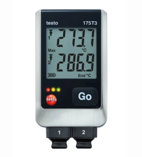
The testo 175 T3 temperature logger with its two connections for external thermocouple probes is a good idea when you would like to record your temperatures at two locations in parallel: for example when measuring the flow and return temperature on radiators. The readings are securely saved in the temperature logger and are available for later measurement data analysis and documentation.
Your advantages
• Practical for frequent and long-term measurements: memory capacity of 1 million readings, up to 3 years’ battery life
• Very large temperature measuring range from -50 °C to +1 000 °C
• Including wall bracket
• Measurement data analysis and documentation: three different software versions to choose from, basic software available as a free download
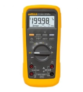
The 87V MAX contains all the trusted features of the most popular DMM in use today, the Fluke 87V, with many more extras.
Withstands drops of up to 4 meters (13 feet)
Fluke's most rugged digital multimeter. The 87V MAX features a rugged case for industrial use and a removable holster. This holster also doubles as a test probe holder for one-handed operation.
IP67 rated
Completely waterproof and dustproof, to work reliably anywhere you need to work.
Heat and cold resistant
This meter has a longer operating temperature range from -40 °C (for up to 20 minutes) to +55 °C.
Another product highlight
- True-rms ac current and voltage for accurate measurements on non-linear signals
- Measures up to 1000 V ac and dc
- Measures up to 10 A (20 A for 30 seconds)
- Frequency up to 200 kHz
- Built-in thermometer allows you to freely take temperature readings without having to carry a separate instrument
- Min/Max/Average recording, plus 250 µs Peak min-max to record variations automatically
- Unique function for accurate measurement of voltage and frequency in variable frequency motor drives and other electrically noisy equipment
- Large digit display, 2 brightness levels, white backlight, and backlit keypad keys for better visibility
- High resolution 19,999 digit mode display
- Long lasting battery life (800 hours)
Available in a range of sizes, this digital caliper is coolant, water and dust proof to IP67 level. It has a large LCD display, fast response speed, dual readout (mm/inch) and can be used for inside, outside, depth and step measuring. Also enables absolute and relative reading.
Extra batteries available - Order Code PAN9042505E 3V Lithium Metal cell
Extra batteries available - Order Code PAN9042505E 3V Lithium Metal cell