Measuring Tools
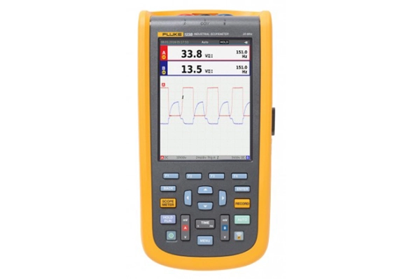
Fluke 123B Industrial ScopeMeter Hand-Held Oscilloscope, 20 MHz
Fluke 123B Offers
Compact and rugged, this oscilloscope is ideal for industrial electrical and electro-mechanical equipment troubleshooting and maintenance applications. Features innovative functions that help technicians troubleshoot faster for quicker results and to keep their systems running smoothly. Additionally, triggering displays waveforms without having to adjust amplitude, timebase, and trigger settings
Features
- Key measurements: Power waveforms with numerical values including resistance, diode, continuity and capacitance measurements
- Automatically capture, view and analyze complex waveforms: Fluke Connect and View™ triggering automatically displays waveforms without having to adjust amplitude, timebase and trigger settings, while Intellaset™ technology analyzes the signal and automatically displays critical numerical readings, making troubleshooting faster than ever
- View data locally on the instrument, or via Fluke Connect mobile app
- Dual-input digital oscilloscope and multimeter
- 20 MHz oscilloscope bandwidth
- Two 5000-count True RMS digital multimeters
- Connect-and-View trigger simplicity for hands-off operation
- IntellaSet technology automatically and intelligently adjusts numerical readout based on the measured signal
- Dual-input waveform and meter reading recorder for trending data over extended periods
- Recorder Event Detect captures elusive intermittent signals on repetitive waveforms up to 4 kHz
- Shielded test leads for oscilloscope, resistance and continuity measurements
- Resistance, continuity, diode and capacitance meter measurements
- Power measurements (W, VA, VAR, PF, DPF, Hz)
- Save or recall data and instrument setups
- Store instrument setups defined by a test sequence for routine maintenance or most often used test procedures
- External optically isolated USB interface to transfer, archive and analyze scope or meter data
- Optional WiFi adapter connected to internal USB port to wirelessly transfer information to the PC, laptop or Fluke Connect mobile app
- Rugged design to withstand 3 g Vibration, 30 g shock, and rated IP51 according to EN/IEC60529
- Highest safety rating in the industry: safety rated for CAT IV 600 V
Connect-and-View triggering for an instant, stable display
Oscilloscope users know how difficult triggering can be. Using the wrong settings can lead to unstable waveform captures, and sometimes the wrong measurement data. This instrument's unique Connect-andView triggering technology recognizes signal patterns and automatically sets up the correct triggering to provide a stable, reliable, and repeatable display. Connect-and-View triggering is designed to work with virtually any signal, including motor drives and control signals - without adjusting parameters, or even touching a button. Signal changes are instantly recognized and settings are automatically adjusted, providing a stable display even when measuring multiple test points in quick succession.
IntellaSet/AutoReading
The Auto Readings function with Fluke IntellaSet technology uses proprietary algorithms to intelligently analyze the measured waveform and automatically displays the most appropriate numerical measurements on the screen, so you can get the data you need easier than ever before. As an example, when the measured waveform is a line voltage signal, the Vrms and Hz readings are automatically displayed, whereas if the measured waveform is a square wave, the Vpeak-peak, and Hz readings are automatically displayed. Using IntellaSet technology in conjunction with Connect-and-View automatic triggering you can be sure you're seeing not only the correct waveform but the appropriate numerical reading as well. All without touching a button.
Industrial equipment needs a reliable power supply to operate properly, use the dual input to obtain key power measurements
For single-phase or 3-phase balanced systems, the dual inputs of this industrial ScopeMeter can measure AC+DC RMS voltage on channel A and AC+DC RMS current on channel B.
One test lead to measure multiple electrical parameters
High-frequency waveform, meter, capacitance, and resistance measurements as well as continuity checks are all covered by a single set of shielded test leads. No time is wasted finding or swapping leads.
Fluke Connect mobile app compatibility
Automated industrial machinery is harder than ever to troubleshoot. It's not enough to just know where you have to test, you also have to know what to look for and that can be hard without baseline measurement data or access to subject matter experts. This Fluke Connect Assets wireless system of software and wireless test tools enables technicians to reduce maintenance costs and increase uptime with accurate equipment records and maintenance data that is easy to interpret, and share. Compare and contrast test point measurement data and trends so you can better understand signal characteristics and changes over time. And, by storing maintenance data on the Fluke Cloud you can enable team members to access it from wherever and whenever they need to so you can get advice or approvals in the field and get your systems up and running faster than ever before.
Use the comprehensive recorder modes to help find intermittent faults with ease
The toughest faults to find are those that happen only once in a while-intermittent event. They can be caused by bad connections, dust, dirt, corrosion, or simply broken wiring or connectors. Other factors, like line outages and sags or the starting and stopping of a motor, can also cause intermittent events resulting in equipment shutdowns. When these events happen, you may not be around to see them. But, your ScopeMeter test tool will. You can either plot the minimum and maximum peak measurement values or record the waveform trace. And, with expandable micro SD memory, recording sessions can be done for up to 14 days. This recorder is even more powerful with the addition of Recorder Event Detect, which makes detecting and logging intermittent faults easier than ever. Just set a threshold on a meter reading or scope trace and deviations are tagged as unique events. You no longer need to search through masses of data to pinpoint faults, and can quickly step from one tagged event to the next, while still having access to the full data set.
Download
Products Lainnya
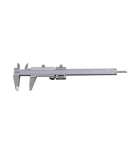
Metric & Inch Reading - Graduation: 0.02mm/0.001"
Incorporating Quadri feature - gives outside, inside, depth and step readings.
Fine adjustment feature allows improved sensitivity of slider movement.
14° vernier face angle reduces parallax.
Satin chrome finish with clear easy read graduations.
Incorporating Quadri feature - gives outside, inside, depth and step readings.
Fine adjustment feature allows improved sensitivity of slider movement.
14° vernier face angle reduces parallax.
Satin chrome finish with clear easy read graduations.
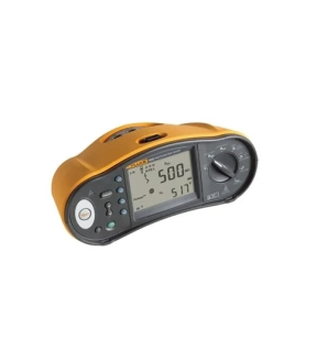
Fluke 1662 menawarkan keandalan Fluke, pengoperasian yang mudah, dan semua kemampuan pengujian yang diperlukan untuk pengujian instalasi sehari-hari.
Fitur utama
Fluke 1662 memberi lebih banyak daya di tangan Anda dengan menguji semua pengaturan lokal secara cepat dan efisien.
Fungsi pengukuran
• Fungsi pengukuran
• Tegangan & frekuensi
• Pemeriksa polaritas perkabelan, mendeteksi kerusakan kabel N
• Resistansi insulasi
• Kontinuitas & resistansi
• Pengukuran kumparan motor dengan pengujian kontinuitas
• Resistansi loop & line
• Prospective earth fault current (PEFC/IK)
• Prospective short-circuit current (PSC/IK)
• Waktu switching RCD
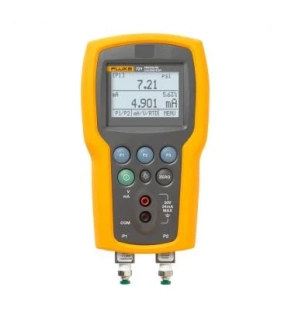
Fluke 721 Precision Pressure Calibrator provides pressure calibration and temperature measurement for custody transfer applications
The Fluke 721 Precision Pressure Calibrator is the ideal tool for gas custody transfer applications. It features dual isolated pressure sensors to allow you to take simultaneous static and differential pressure measurements with a single tool. And it can be configured by selecting either a 16 psi (1.1 bar) or 36 psi (2.48 bar) low pressure sensor then adding any of seven high pressure ranges: 100, 300, 500, 1000, 1500, 3000 or 5000 psi (6.9, 20, 24.5, 69, 103.4, 200, 345 bar).
Other useful features:
- Measures up to 30 V DC, checks 24 V loop power supplies
- Extends pressure measurement range with connection to external 750P
- 750 series pressure modules (50 ranges)
- Provides a large backlit graphic display that can show up to three inputs simultaneously
- Stores five instrument setups for recall
Now there is one intrinsically safe digital multimeter (DMM) you can use in IIC (gas), in Zones 1 and 2, and IIIC (dust), Zones 21 and 22. Whether you work in an oil, chemical, or pharmaceutical environment , all the test and troubleshooting capabilities you need are in the most robust and intrinsically secure (IS) Fluke DMM ever made. The Fluke 28 II Ex is also water, dust and drop resistant. You will be equipped to solve all problems, inside and outside the danger zone, without compromising on compliance or measurement performance.